Matrice IO_MUX et GPIO (GPIO, IO_MUX)
publication: 26 décembre 2021 / mis à jour 27 décembre 2021

Aperçu
La puce ESP32 dispose de 34 pads GPIO physiques. Chaque pad peut être utilisé comme E/S à usage général ou être connecté à un signal périphérique interne. Les IO_MUX, RTC IO_MUX et la matrice GPIO sont responsables du routage des signaux des périphériques aux pads GPIO. Ensemble, ces systèmes fournissent des E/S hautement configurables.
Notez que les pads GPIO d'E/S sont 0-19, 21-23, 25-27, 32-39, tandis que les GPIO de sortie sont 0-19, 21-23, 25-27, 32-33. Les pads GPIO 34-39 sont en entrée uniquement.
Nous décrivons ici la sélection du signal et la connexion entre les plots numériques (FUN_SEL, IE, OE, WPU, WDU, etc.), 162 signaux d'entrée périphériques et 176 signaux de sortie (signaux de contrôle : SIG_IN_SEL, SIG_OUT_SEL, IE, OE, etc.), des signaux d'entrées/sorties périphériques rapides (signaux de commande: IE, OE, etc.), et RTC IO_MUX.
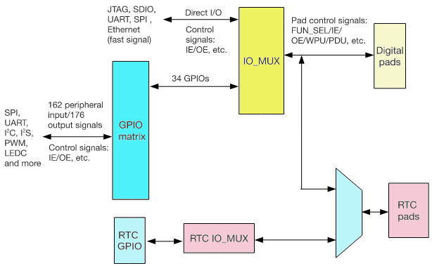
- IO_MUX contient un registre par pad GPIO. Chaque pad peut être configuré pour exécuter une fonction "GPIO"
(lorsqu'il est connecté à la matrice GPIO) ou une fonction directe (en contournant la matrice GPIO). Certains à grande vitesse
les fonctions numériques (Ethernet, SDIO, SPI, JTAG, UART) peuvent contourner la matrice GPIO pour une meilleure haute fréquence
performances numériques. Dans ce cas, l'IO_MUX permet de connecter ces plots directement au périphérique.)
- La matrice GPIO est une matrice de commutation complète entre les signaux d'entrée/sortie périphériques et les pads.
- Pour l'entrée sur la puce: chacune des 162 entrées périphériques internes peut sélectionner n'importe quel pad GPIO comme entrée source.
- Pour la sortie de la puce: le signal de sortie de chacun des 34 pads GPIO peut provenir de l'un des 176 pads signaux de sortie périphériques.
- RTC IO_MUX est utilisé pour connecter les pads GPIO à leurs fonctions analogiques et basse consommation. Seul un sous-ensemble de GPIO les pads ont ces fonctions optionnelles «RTC».
Entrée périphérique via la matrice GPIO
Sommaire
Pour recevoir un signal d'entrée périphérique via la matrice GPIO, la matrice GPIO est configurée pour générer le périphérique l'indice d'entrée du signal (0-18, 23-36, 39-58, 61-90, 95-124, 140-155, 164-181, 190-195, 198-206) de l'un des 34 GPIO (0-19, 21-23, 25-27, 32-39).
Le signal d'entrée est lu depuis le pad GPIO via le IO_MUX. L'IO_MUX doit être configuré pour définir le choix pad à la fonction "GPIO". Cela provoque le routage du signal d'entrée du pad GPIO dans la matrice GPIO, qui à son tour l'achemine vers l'entrée périphérique sélectionnée.
Description fonctionnelle
Cette figure montre la logique de sélection d'entrée via la matrice GPIO.
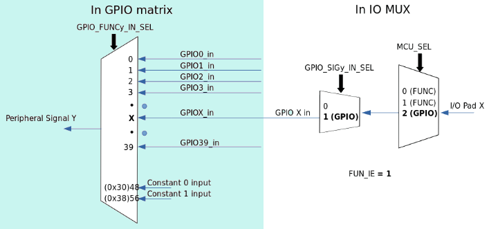
Pour lire le pad GPIO X dans le signal périphérique Y, suivez les étapes ci-dessous :
- Configurez le registre GPIO_FUNCy_IN_SEL_CFG correspondant au signal périphérique Y dans la matrice GPIO :
- Définissez le champ GPIO_FUNCy_IN_SEL dans ce registre, correspondant au pad GPIO X à lire. Dégager tous les autres champs correspondant aux autres pads GPIO.
- Configurez le registre GPIO_FUNCx_OUT_SEL_CFG et effacez le champ GPIO_ENABLE_DATA[x] correspondant
au pad GPIO X dans la matrice GPIO :
- Définissez le bit GPIO_FUNCx_OEN_SEL dans le registre GPIO_FUNCx_OUT_SEL_CFG pour forcer la broche état de sortie à déterminer toujours par le champ GPIO_ENABLE_DATA[x].
- Le champ GPIO_ENABLE_DATA[x] est un bit dans GPIO_ENABLE_REG (GPIOs 0-31) ou GPIO_ENABLE1_REG (GPIO 32-39). Effacez ce bit pour désactiver le pilote de sortie pour le pad GPIO.
- Configurez l'IO_MUX pour sélectionner la matrice GPIO. Définir le registre IO_MUX_x_REG correspondant à GPIO
pad X comme suit :
- Définissez le champ de fonction (MCU_SEL) sur la fonction IO_MUX correspondant à GPIO X (il s'agit de la fonction #3—valeur numérique 2—pour toutes les broches).
- Activez l'entrée en définissant le bit FUN_IE.
- Définissez ou effacez les bits FUN_WPU et FUN_WPD, comme vous le souhaitez, pour activer/désactiver le pull-up/pull-down de résistances internes.
Notes:
- One input pad can be connected to multiple input_signals.
- The input signal can be inverted with GPIO_FUNCy_IN_INV_SEL.
- It is possible to have a peripheral read a constantly low or constantly high input value without connecting
this input to a pad. This can be done by selecting a special GPIO_FUNCy_IN_SEL input, instead of a GPIO
number:
- When GPIO_FUNCy_IN_SEL is 0x30, input_signal_x is always 0.
- When GPIO_FUNCy_IN_SEL is 0x38, input_signal_x is always 1.
For example, to connect RMT peripheral channel 0 input signal (RMT_SIG_IN0_IDX, signal index 83) to GPIO 15, please follow the steps below. Note that GPIO 15 is also named the MTDO pin:
- Set the GPIO_FUNC83_IN_SEL_CFG register field GPIO_FUNC83_IN_SEL value to 15.
- As this is an input-only signal, set GPIO_FUNC15_OEN_SEL bit in GPIO_FUNC15_OUT_SEL_CFG_REG.
- Clear bit 15 of GPIO_ENABLE_REG (field GPIO_ENABLE_DATA[15]).
- Set the IO_MUX_GPIO15 register MCU_SEL field to 2 (GPIO function) and also set the FUN_IE bit (input mode).
Simple GPIO Input
The GPIO_IN_REG/GPIO_IN1_REG register holds the input values of each GPIO pad.
The input value of any GPIO pin can be read at any time without configuring the GPIO Matrix for a particular peripheral signal. However, it is necessary to enable the input in the IO_MUX by setting the FUN_IE bit in the IO_MUX_x_REG register corresponding to pad X, as mentioned in Section 4.2.2.
Peripheral Output via GPIO Matrix
To output a signal from a peripheral via the GPIO Matrix, the GPIO Matrix is configured to route the peripheral output signal (0-18, 23-37, 61-121, 140-125, 224-228) to one of the 28 GPIOs (0-19, 21-23, 25-27, 32-33).
The output signal is routed from the peripheral into the GPIO Matrix. It is then routed into the IO_MUX, which is configured to set the chosen pad to ”GPIO” function. This causes the output GPIO signal to be connected to the pad.
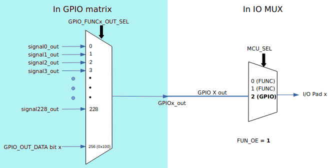
To output peripheral signal Y to particular GPIO pad X, follow these steps:
- Configure the GPIO_FUNCx_OUT_SEL_CFG register and GPIO_ENABLE_DATA[x] field corresponding to
GPIO X in the GPIO Matrix:
- Set the GPIO_FUNCx_OUT_SEL field in GPIO_FUNCx_OUT_SEL_CFG to the numeric index (Y) of de- sired peripheral output signal Y.
- If the signal should always be enabled as an output, set the GPIO_FUNCx_OEN_SEL bit in the GPIO_FUNCx_OUT_SEL_CFG register and the GPIO_ENABLE_DATA[x] field in the GPIO_ENABLE_REG register corresponding to GPIO pad X. To have the output enable signal decided by internal logic, clear the GPIO_FUNCx_OEN_SEL bit instead.
- The GPIO_ENABLE_DATA[x] field is a bit in either GPIO_ENABLE_REG (GPIOs 0-31) or GPIO_ENABLE1_REG (GPIOs 32-39). Clear this bit to disable the output driver for the GPIO pad.
- For an open drain output, set the GPIO_PINx_PAD_DRIVER bit in the GPIO_PINx register corresponding to GPIO pad X. For push/pull mode (default), clear this bit.
- Configure the IO_MUX to select the GPIO Matrix. Set the IO_MUX_x_REG register corresponding to GPIO
pad X as follows:
- Set the function field (MCU_SEL) to the IO_MUX function corresponding to GPIO X (this is Function #3—numeric value 2—for all pins).
- et the FUN_DRV field to the desired value for output strength (0-3). The higher the drive strength, the more current can be sourced/sunk from the pin.
- If using open drain mode, set/clear the FUN_WPU and FUN_WPD bits to enable/disable the internal pull-up/down resistors.
Notes:
- The output signal from a single peripheral can be sent to multiple pads simultaneously.
- Only the 28 GPIOs can be used as outputs.
- The output signal can be inverted by setting the GPIO_FUNCx_OUT_INV_SEL bit.
Simple GPIO Output
The GPIO Matrix can also be used for simple GPIO output – setting a bit in the GPIO_OUT_DATA register will write to the corresponding GPIO pad.
To configure a pad as simple GPIO output, the GPIO Matrix GPIO_FUNCx_OUT_SEL register is configured with a special peripheral index value (0x100).
Legal: site web personnel sans commerce / personal site without seling